Apparently it is challenging to use LM358 for audio applications – but I want to try anyway for analog synthesizer. By adding a output resistor to ground, you force the amp into class A mode, and the distortion is much less. https://www.sound-au.com/articles/lm358.htm
Category: electronics
TL866ii Vpp programming adapter
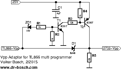
Programming adapter to allow for higher Vpp programming voltages ZD1 should be approximately 3V lower than max Vpp – use lab power supply on 25V line.
https://www.dr-bosch.com/volker/umbau/index.html

D1 is BAT49 – but probably 1N4148 will work fine here, BC817 / BC807 probably can be any small transistors: 2N3904/2N3906
8-bit IDE interface
Divide by 3 and 5 circuits
Found this link has some good circuits. https://pages.mtu.edu/~suits/electronics/Divide_by_3&5_circuit.html
Copied here if page goes down:
I was interested in generating a 40 Hz clock with close to a 50% duty cycle starting a signal derived from line power. In the U.S., line power is at 60Hz, so doubling that to 120 Hz, then dividing bt three would yield 40 Hz. In much of the rest of the world line power is 50 Hz. That can be doubled twice to get 200 Hz, which can then be divided by 5 to get 40 Hz.
There are, of course, a number of ways to divide by 3 or 5. It is a little more challenging to end up with something approaching a 50% duty cycle. You could program your Arduino to do it, if nothing else. However, I took the challenge to be to do it with minimal component cost and minimal parts count.
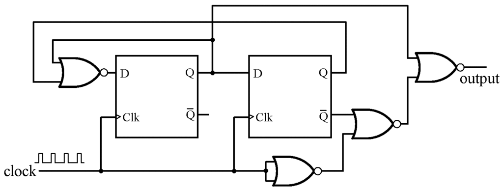
I found several divide by three circuits on the internet, however the chip count seemed higher than necessary. After some thought, I came up with a divide by three circuit that uses two 14-pin integrated circuits that I had in my “junk box:” a 74LS74 dual flip-flop and a 74LS02 quad NOR gate. If the clock has a 50% duty cycle, the output of the divider also has a 50% duty cycle.
More generally, if the clock has a duty cycle equal to D, this circuit will output with a duty cycle of (2-D)/3, which is always closer to 50% than D. The outputs from either of the flip-flops will be at the clock frequency divided by 3, but with a 33% (or 66%) duty cycle. The extra three NORs, which are already there, are used to make the output closer to a 50% duty cycle.

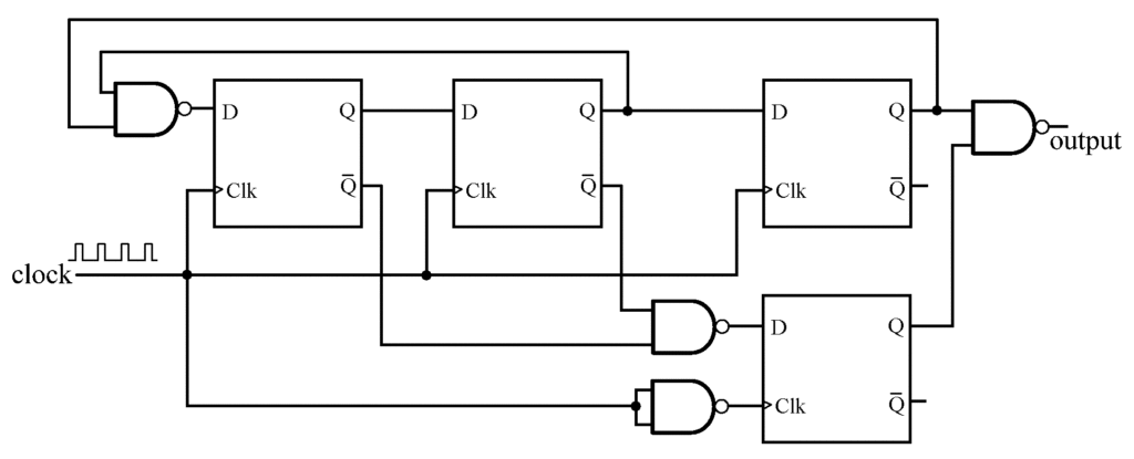
For those who might need a divide by 5, I came up with one that uses three 14-pin logic ICs – two dual D flip-flops and a quad NAND. This divide by five will have a duty cycle equal to (3-D)/5, which is also always closer to 50% than is the input clock.

The circuits shown use an edge-triggered flip-flop that triggers on the rising edge (e.g., a 7474). If your flip-flops trigger on the falling edge, no changes are necessary for the divide by 5 circuit, and the divide by 3 circuit only needs to have the NOR inverter to be relocated. Oscilloscope traces are shown below (sorry, I switched the channel 1 and 2 cables, but did not notice until later).