Apparently it is challenging to use LM358 for audio applications – but I want to try anyway for analog synthesizer. By adding a output resistor to ground, you force the amp into class A mode, and the distortion is much less. https://www.sound-au.com/articles/lm358.htm
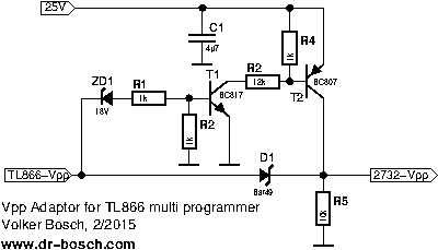
TL866ii Vpp programming adapter
Programming adapter to allow for higher Vpp programming voltages ZD1 should be approximately 3V lower than max Vpp – use lab power supply on 25V line.
https://www.dr-bosch.com/volker/umbau/index.html
D1 is BAT49 – but probably 1N4148 will work fine here, BC817 / BC807 probably can be any small transistors: 2N3904/2N3906
Best links I’ve found:
bdos calls: http://www.shaels.net/index.php/cpm80-22-documents
https://www.seasip.info/Cpm/bdos.html
CPM3 for S100 http://www.s100computers.com/Software%20Folder/CPM3%20BIOS%20Installation/CPM3%20HDISK%20BIOS%20Software.htm
CPM3 https://forum.vcfed.org/index.php?threads/installing-cp-m-3-plus-on-a-home-built-z80-computer.61802/
ISIS/PLM https://www.retrotechnology.com/restore/isis.html
General info: http://primrosebank.net/computers/cpm/cpm_about.htm
XModem for Z80
I wanted to implement a XModem to incorporate into the Z80 monitor program for my CPUVille Z80. It needed to be small to fit in the 2K ROM monitor, the whole thing ends up being 264 additional bytes. Here is the code for that:
; based on 6502 version http://www.6502.org/source/io/xmodem/xmodem-receive.txt
; re-coded by Tom Lovie 2023-03-23
; sub write_string and put_chr are already in ROM
monitor_warm_start: equ 0450h
SOH equ 01h ; start block
EOT equ 04h ; end of text marker
ACK equ 06h ; good block acknowledged
NAK equ 15h ; bad block acknowledged
CAN equ 18h ; cancel (not standard, not supported)
CR equ 0dh ; carriage return
LF equ 0ah ; line feed
ESC equ 1bh ; ESC to exit
rbuff: equ 0c00h ; page aligned receive buffer
rbuffp: equ 0ch ; page of receive buffer
sbuff: equ 1000h ; storage buffer to place received data
sbuffp: equ 10h ; storage buffer page
org 0800h
call XModem
jp monitor_warm_start
XModem:
ld hl,msg
call write_string
ld hl,sbuff
ld (ptr),hl ; initialize the storage pointer
ld a,01h
ld (blkno),a ; start at block number 1
StartX: ld a,NAK ; Start in CRC mode - no fallback
call put_chr ; send it
ld a,00h ; loop counter in a
call GetByte ; try to get a byte
jr c,GotByte
jr nc,StartX ; if not try again
StartBlk: ld a,00h ; loop counter in a
call GetByte ; try to get a byte
jr nc,StartBlk
GotByte: cp ESC ; want to quit
ret z
cp SOH ; start of block?
jr z,BegBlk
cp EOT ; end of text
jr nz,BadCrc
jr Done
BegBlk: ld hl,rbuff ; start hl at the receive buffer
GetBlk: ld a,00h ; 3 second window to receive char
GetBlk1: call GetByte ; get next char
jr nc,BadCrc ; just sending NAK
GetBlk2: ld (hl),a ; store the character in buffer
inc hl ; increment the buffer
ld a,83h
cp l ; <01><FE><128 bytes><CHKSUM>
jr nz,GetBlk ; get 131 characters (0x83)
ld l,00h ; start at beginning of buffer
ld a,(blkno) ; actual block number
cp (hl) ; sent block number
jr z,GoodBlk1 ; block number is expected
jr ErrorOut ; error out of the xmodem routine
GoodBlk1: xor 0ffh ; compliment the actual block no
inc hl
cp (hl) ; compare to second byte
jr z,GoodBlk2 ; block number compliment
jr ErrorOut ; error out of the xmodem routine
GoodBlk2: ld h,rbuffp ; point hl at the receive buffer
ld l,81h ; last byte
ld a,00h ; initialize a
CalcCrc: add (hl) ; compute running total start 82h
dec l
jr nz,CalcCrc
add a,(hl) ; do the block number as well
inc a ; because blockno + cpl = 255.
ld l,82h ; (hl) is the checksum
cp (hl)
jr z,GoodCrc
BadCrc: call Flush ; flush serial buffer
ld a,NAK ; and send
call put_chr ; a NAK
jr StartBlk ; restart the block
GoodCrc: ld l,02h ; hl is now pointing data
ld de,(ptr) ; de is now pointing storage
ld c,80h ; 128 bytes
ld b,00h ;
ldir ; copy the block
ld (ptr),de ; store the current pos
ld a,(blkno) ; load the block number
inc a
ld (blkno),a ; store the block number back
ld a,ACK ; send ACK
call put_chr
jp StartBlk ; get next block
Done: ld a,ACK
call put_chr
call Flush
ld hl,good ; load success message
call write_string
ret
ErrorOut: ld hl,err ; print error message and exit
call write_string
call Flush ; discard remaining buffer
ret ; return after fatal error
; subroutine to wait a set amount of time to get a byte
; Byte will be in A, destroys BC (delay loop)
GetByte: ld b,a
ld c,a
GetByteLoop: call get_chr
ret c ; return if got chr (carry set)
dec c
jr nz,GetByteLoop
dec b
jr nz,GetByteLoop ; delay loop
or a ; clear carry flag
ret
; subroutine to flush the receive buffer
; destroys A
Flush: ld a,80h
call GetByte
jr c,Flush
ret
;Get one byte from the serial port if available.
;Returns with byte in A reg with carry flag set, if carry flag clear means no character available
get_chr: or a ;clear carry flag
in a,(3) ;get status
and 002h ;check RxRDY bit
ret z ;not ready, quit
in a,(2) ;get char
scf ;set carry flag we got a char
ret
ptr: dfw 0
blkno: dfb 0
err: dfb "Up Err!",CR,LF,0
good: dfb "Up Ok!",CR,LF,0
msg: dfb CR,LF,"X/CSUM <Esc> to q",CR,LF,0
Been researching how to use DRAM in a homebuilt computer. For interests sake of course, since SRAM is so readily accessable, and much easier to use. DRAM is challenging, considering building a Z80 to try it.
Useful links:
http://www.cpm.z80.de/download/dram.pdf
of course the whole site: http://www.cpm.z80.de/
8-bit IDE interface
Divide by 3 and 5 circuits
Found this link has some good circuits. https://pages.mtu.edu/~suits/electronics/Divide_by_3&5_circuit.html
Copied here if page goes down:
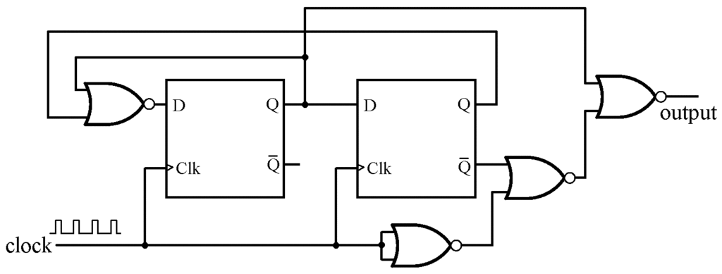
I was interested in generating a 40 Hz clock with close to a 50% duty cycle starting a signal derived from line power. In the U.S., line power is at 60Hz, so doubling that to 120 Hz, then dividing bt three would yield 40 Hz. In much of the rest of the world line power is 50 Hz. That can be doubled twice to get 200 Hz, which can then be divided by 5 to get 40 Hz.
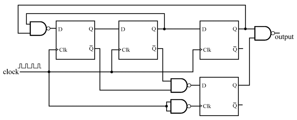
There are, of course, a number of ways to divide by 3 or 5. It is a little more challenging to end up with something approaching a 50% duty cycle. You could program your Arduino to do it, if nothing else. However, I took the challenge to be to do it with minimal component cost and minimal parts count.
I found several divide by three circuits on the internet, however the chip count seemed higher than necessary. After some thought, I came up with a divide by three circuit that uses two 14-pin integrated circuits that I had in my “junk box:” a 74LS74 dual flip-flop and a 74LS02 quad NOR gate. If the clock has a 50% duty cycle, the output of the divider also has a 50% duty cycle.
More generally, if the clock has a duty cycle equal to D, this circuit will output with a duty cycle of (2-D)/3, which is always closer to 50% than D. The outputs from either of the flip-flops will be at the clock frequency divided by 3, but with a 33% (or 66%) duty cycle. The extra three NORs, which are already there, are used to make the output closer to a 50% duty cycle.
For those who might need a divide by 5, I came up with one that uses three 14-pin logic ICs – two dual D flip-flops and a quad NAND. This divide by five will have a duty cycle equal to (3-D)/5, which is also always closer to 50% than is the input clock.
The circuits shown use an edge-triggered flip-flop that triggers on the rising edge (e.g., a 7474). If your flip-flops trigger on the falling edge, no changes are necessary for the divide by 5 circuit, and the divide by 3 circuit only needs to have the NOR inverter to be relocated. Oscilloscope traces are shown below (sorry, I switched the channel 1 and 2 cables, but did not notice until later).
cpm z80 output
Up until now I was using raw serial output for console, but I think this is not the correct way.
write_char:
in a,(3)
and 001h
jp z, write_char
ld a,b
out (2),a
ret
now this works, but it does not work for cpm emulator yaze-ag. I suspect this is because I should be using the syscall to output to the console.
write_char: push de ; preserve register values
push bc
ld c,2 ; function 2
ld e,a ; char to write
call 5 ; call bios / syscall
pop bc ; restore register values
pop de
ret
minicom binary transfer
Found these pages useful http://www.dannysung.com/articles/linux/tips/sending-binary-files-via-minicom/
https://gist.github.com/cstrahan/5796653
google search for minicom binary transfer
another option is to use the ascii-xfer program with these options:
/usr/bin/ascii-xfr -esvn
Found this article extremely useful: https://www.fortwayneprinterrepair.com/wordpress/2014/03/17/xerox-phaser-6500-workcentre-6505-light-print-issues/
copy of article below incase the link ever breaks.
Troubleshooting Light Print Issues on the Xerox Phaser 6500 / WorkCentre 6505
I haven’t worked on a whole lot of these machines but one problem that I’ve ran into on more than one occasion is light print issues. Before I get started I want to explain that this article is for light print issues associated with a single color. If you have light print issues with the whole page you might want to move on because this article might not contain the answers your looking for.
First, I get a call to check a machine out that has light print. Upon arrival the customer informs me that over the last few days the print kept getting lighter and lighter. Finally, they replaced the cartridge but unfortunately that didn’t solve the problem. Most times I see this in black as that is the most used cartridge but it could happen in any color. Obviously lots of things can cause this problem but more often than not I’ve been finding it to be an issue with third party cartridges. I’m unsure exactly what happens but it would seem the cartridge runs out of toner before the chip tells the machine it is. Therefore the auger system empties out and the developer unit inside the Drum unit does the same thing. The only way to fix the problem is to put the machine into Diagnostic Mode and pump more toner into the auger and developer.
Troubleshooting Tips
1. Probably the easiest way to see if you have a toner issue is to remove the effected toner and one of the other colors.
2. Remove the Drum Unit – You must remove the cassette tray to open the front cover enough to remove. Careful not to damage or scratch the black transfer belt assembly as this will effect image quality.
3. On the right side, inside the print mech, is the end of the four augers that feed toner into the developer. Typically this area is usually dirty.
4. In the picture below you will see the toner motor gear, move the gear in the direction shown a few times. If there is no toner is the auger system the very little or no toner will come out the end in the front of the machine. Now do the same test from the good color cart that you previously removed. you should notice the difference in the amount of spillage between the two.
Note : For step 5 make sure the toner cartridge you are using is new. Recommend Xerox OEM.
5. If you do find that the auger is empty you will need to put the machine into diagnostic mode and run the toner motor for that selected cartridge. The service manual says to run the test with the cartridge out but in this case we will want to leave the cartridge in. Turn on the motor test for about 30 seconds. Then print off 10 to 20 pages. It might take a few pages to get the color fully restored. Now if that doesn’t work then you could try another 30 seconds. If that still doesn’t work then I would start looking some where else or take the cartridge out, cheat the side interlock switch and verify the motor gear is rotating.
Entering Service Diagnostics
1. Turn the printer Off.
2. Press and hold the Up and Down arrows simultaneously and turn the printer On.
3. Release the buttons when Service Mode and ESS Diag appear on the SFP display, or Service Mode, Printer, and Fax/Scanner appear on the MFP display.
4. Run the Toner Motor test: Engine Diag > Motor Test > (C)(M)(Y)(K) Toner Motor.
Exiting Service Diagnostics
Scroll to Exit Mode, select Complete, then press OK.
Conclusion on the Light Print Issues
Obviously, this article only touches on specific problem with the light print issues. However, I’ve seen this enough to know it’s a real problem with these Xerox and Dell models. I hope this will help others find solutions to there problems. Not every problem is the same and this might not be the fix for your particular issue. If anything it might help you rule out several parts of the machine.